Plasmonic Invisibility
- Edwards B, Alu A, Silveirinha M, Engheta N. "Experimental Verification of Plasmonic Cloaking at Microwave Frequencies" Physical Review Letters. (103) 2009. (pdf)
Introduction
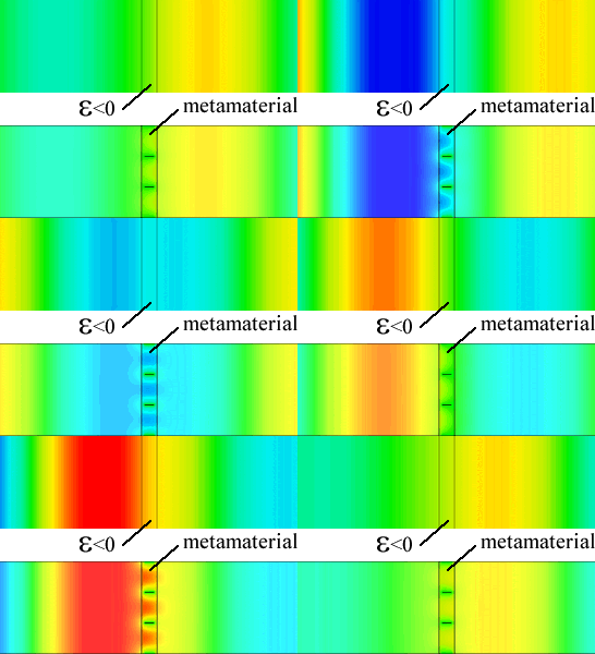
Plasmonic material (top) and a plasmonic metamaterial (bottom). The metamaterial consists of perfect conductors and high permittivity dielectrics. The interaction with an incident wave is similar when viewed from the outside.
To understand this project we must understand the basics of Mie Scattering. When an electromagnetic wave is incident on an object it will scatter the light. It is this scattered light that we see and by which we know the object is there. For objects that are less than a few wavelengths in size, the scattering can be expressed as the first few terms of a harmonic expansion (dipole, quadrupole, etc) with the majority of the energy going into the dipolar term. Put more simply, while different small objects may scatter a wave with different intensities, the scattered wave always has the same basic shape, that of the dipole radiation pattern caused by the dipole moment of the scatterer.
If we can cancel out this first dipolar term, the remainder of the scattering is likely to be very faint. In a very similar manner to a diver attempting to reach neutral weight by combining his buoyant body with very dense lead, in this project, we attempted to reach an electromagnetic neutrality by balancing the generally positive permittivity of a test object with the negative permittivity of a metamaterial cloak. When the plasmonic cloak is properly designed, this dipole radiation can be completely canceled out to leave only the lower power higher-order scattering modes.
Plasmonic materials are readily found in nature at optical frequencies in the form of gold, silver, and many other metals. However, there are no naturally available plasmonic materials in the RF and microwave regime. Therefore we needed to build our own using a metamaterial technique first discussed by Walter Rotman in the early 60's. I'll attempt to explain it without going into much mathematics. When electromagnetic energy is incident on a slab of plasmonic material, it will penetrate it evanescently, similar to electron tunneling. A small portion of the energy will appear on the other side and much of it will be reflected. Similarly, when an electromagnetic wave is incident on a waveguide for which its frequency is below cut-off, some of the field will penetrate this section, continuing on the other side, while much of it will be reflected. Therefore, a waveguide below cutoff (or several of them near each other) and a bulk plasmonic material can interact with an electromagnetic wave in a very similar fashion.
This is apparent in the figure above, which shows a transverse electric (TE) wave incident on a plasmonic and metamaterial slab. In both cases the wave is incident and transmitted into vacuum. The plasmonic material has a relative permittivity less than zero, while the metamaterial is made of a material with a permittivity greater than one and has evenly spaced metal fins. However, despite the radically different geometries and materials, the effect on the field is almost identical.
Our object to be cloaked consists of a dielectric cylinder (shown in white). This was wrapped in our plasmonic metamaterial consisting of copper plates immersed in Acetone (blue in rendering). This is sandwiched in a parallel plate geometry to force the waves to behave as a 2D system.
Rendering of target object (white) and cloak (copper fins and blue fluid).
Experiment design.
Experimental configuration. A 4'x8' optical table rimmed with graphite impregnated absorbers and a subwavelength mesh on top. The illiumination probe is shown in the foreground while the cloaked object is shown in the background.
Measurements of both the total field and incident field were taken on a grid surrounding both the cloaked and uncloaked object. The difference between the total field and incident is the scattered field. This is shown to the left. In the uncloaked object, the scattered field shows strong forward scattering (the shadow) and the total field shows a discontinuity in the incident plane wave. The cloaked object's scattered field is comparatively small and the incident wave largely passes through it without disruption.
By comparing the relative scattered power between the cloaked and uncloaked object, we could determine the efficacy of our design. This is done through a concept of Scattering Cross Section (SCS). A piece of black paper has an SCS equal to its area because it absorbs all light incident on it. An equivalently sized aluminum foil would have twice this SCS as it would also be reflecting light. An invisible object would have an SCS of zero. We found that at the design frequency in theory, simulation and experiment there was a dramatic dip in the relative SCS for the cloaked structure. For that at lease one frequency, the dielectric cylinder becomes nearly invisible.


